PERFORMANCE CHARACTERISTICS
◎Integrated fuselage is welded with steel plate
◎The drive shaft is driven by a flywheel with or without aears depending on the speed and capability of the slider and the point of occurrence.
◎The design of a connecting rod with the combination of crankshaft and cass ette slider absorbs the high load and resistance produced by high speed stamping.
STRUCTURAL ANALYSIS
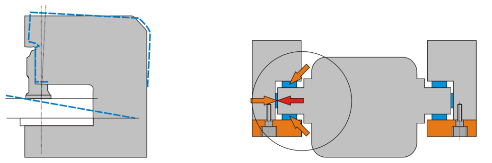
Ultra-high rigid body High-precision six-sided guide

The structural rigidity of the frame is The ultra-long guide rail has high precision,
also changed and designed to ensure the lateral force is directly absorbed by the body,
high rigidity and die life of the frame. and the guide rail has high precision and stability.
Main Technical Parameter
| Item | Specifcation | SDP-25S | SDP-35S | SDP-45S | SDP-60S | SDP-80S | SDP-110S | SDP-160S | SDP-200S | SDP-260S | SDP-315S | SDP-400S | |||||||||||
| Model | V | H | V | H | V | H | V | H | V | H | V | H | V | H | V | H | V | H | V | H | V | H | |
| Capacity | ton | 25 | 35 | 45 | 60 | 80 | 110 | 160 | 200 | 260 | 315 | 400 | |||||||||||
| Rated tonnage point | mm | 3.2 | 1.6 | 3.2 | 1.6 | 3.2 | 1.6 | 4 | 2 | 4 | 2 | 6 | 3 | 6 | 3 | 6 | 3 | 7 | 3.5 | 7 | 3.5 | 8 | |
| Stroke | s.p.m | 60-140 | 130-200 | 40-120 | 110-180 | 40-110 | 100-150 | 40-120 | 80-120 | 35-80 | 80-120 | 30-60 | 60-90 | 20-50 | 40-70 | 20-50 | 50-70 | 20-40 | 40-50 | 20-35 | 30-45 | 15-30 | |
| Speed changing | s.p.m | 110 | 85 | 75 | 65 | 65 | 50 | 35 | 35 | 30 | 35 | 30 | |||||||||||
| Stable speed | mm | 70 | 30 | 70 | 40 | 80 | 50 | 120 | 60 | 150 | 70 | 180 | 80 | 180 | 90 | 200 | 100 | 250 | 150 | 250 | 150 | 300 | |
| Die height | mm | 195 | 215 | 220 | 235 | 250 | 265 | 310 | 340 | 340 | 380 | 360 | 410 | 360 | 510 | 460 | 510 | 500 | 550 | 550 | 600 | 550 | |
| Slide adjustment | mm | 50 | 55 | 60 | 75 | 80 | 80 | 100 | 110 | 120 | 120 | 150 | |||||||||||
| Feane Gap | mm | 800 | 800 | 800 | 800 | 800 | 800 | 800 | 800 | 800 | 800 | 800 | |||||||||||
| Bolster area | mm | 680*300*70 | 800*400*70 | 850*440*80 | 900*500*80 | 1000*550*90 | 1150*600*110 | 1250*800*140 | 1400*820*160 | 1500*840*180 | 1600*860*190 | 1800*880*220 | |||||||||||
| Slide area | mm | 300*220*50 | 360*250*50 | 400*300*60 | 500*360*70 | 560*420*70 | 650*470*70 | 700*550*90 | 850*630*90 | 950*700*100 | 1130*720*100 | 1300*810*105 | |||||||||||
| Shank hole | kw*p | φ38.1 | φ38.1 | φ38.1 | φ50 | φ50 | φ50 | φ65 | φ65 | φ65 | φ65 | φ80 | |||||||||||
| Main motor | (VS)3.7*4 | (VS)3.7*4 | (VS)5.5*4 | (VS)5.5*4 | (VS)7.5*4 | (VS)11*4 | (VS)15*4 | (VS)18.5*4 | (VS)22*4 | (VS)30*4 | (VS)37*4 | ||||||||||||
| Slide adjust device | kw*p | Manual | Manual | Manual | Manual | Electric | Electric | Electric | Electric | Electric | Electric | Electric | |||||||||||
| Air pressure | 6 | 6 | 6 | 6 | 6 | 6 | 6 | 6 | 6 | 6 | 6 | ||||||||||||
| Presses precision | mm | ||||||||||||||||||||||
| Presses weight | ton | 3.5 | 4.7 | 6.5 | 8 | 9.8 | 16.5 | 21 | 28 | 40 | 45 | 55 | |||||||||||
| Die cushion capacity | ton | 2.3 | 2.3 | 3.6 | 3.6 | 6.3 | 10 | 14 | 14 | 14 | 14 | ||||||||||||
| Die cushion stroke | mm | 50 | 50 | 70 | 70 | 80 | 80 | 100 | 100 | 100 | 100 | ||||||||||||
| Die cushion effective area | mm² | 300*230 | 300*230 | 350*300 | 450*310 | 500*350 | 650*420 | 710*480 | 810*480 | 810*480 | 810*48 | ||||||||||||